一、项目名称:
NFC门锁
二、项目概述:
本系统是基于双核LPC55S69为主控芯片的NFC门锁,采用I2C端口读取NFC读卡器的数据,经过身份验证后,启动伺服电机控制门锁开锁。延时后再次扫描读卡器,如果没有更新并保持的最新读卡器数据后,控制伺服电机返回,关闭门锁。
补充说明:原计划的门锁是采用Tensorflow Lite的智能门锁项目,用摄像头扫描,捕捉人体接近并启动图片识别功能,符合安全身份认证后,开启门锁。原计划中,NFC门锁是其中的一个多重身份验证工具,运行在Core0在低功耗运行。CV识别运行在core1,高速执行。
LPC55S69本身功能强大,可以胜任告诉图片读取的功能,但是在导入tensorflow lite的过程中,发现了公版model的问题,就是这个系统太大,不能支持MCU的运行。tensorflow lite对于内存的最小要求是1M内存,680k闪存已经足够大,但是不能支持经过测试的公版model(如mobileNet-0.25x0.25执行flatten后仍然有1.68M)。
自行设计model并训练更小的模型,在性能上不能得到验证,所以在提交截止期之前,只能实现现有的功能。
感谢本次挑战赛的开发过程,引出了一个有趣的新题目,就是如何在高性能MCU上执行大的模型运行,如VGG这样的深度网络模型,后续仍然继续沿着这个思路开发,力争在这个板子上实现公版模型的适用。
经过多次实验,已经有了初步的设计框架:在不启动MMU功能的情况下,如何构建一个SWAP空间,仍然能够快速实现扩址访问,只需要再做一个overlay的内存管理库就可以了。
三、作品实物图
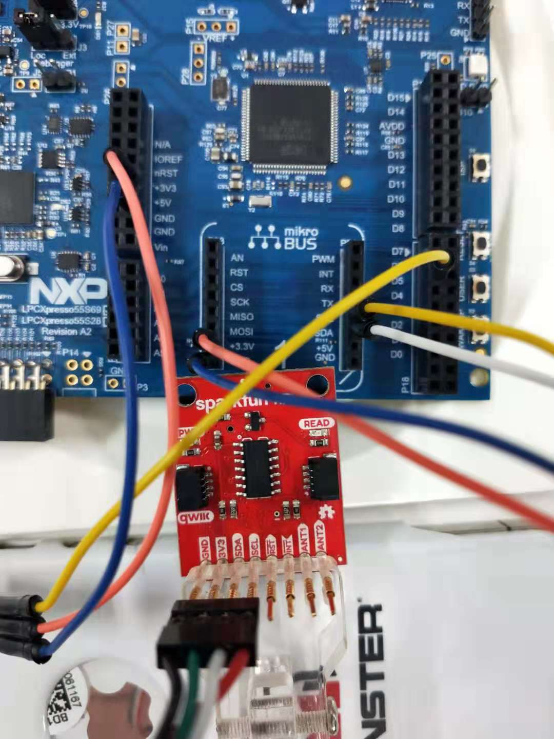
NFC读卡器的链接I2C
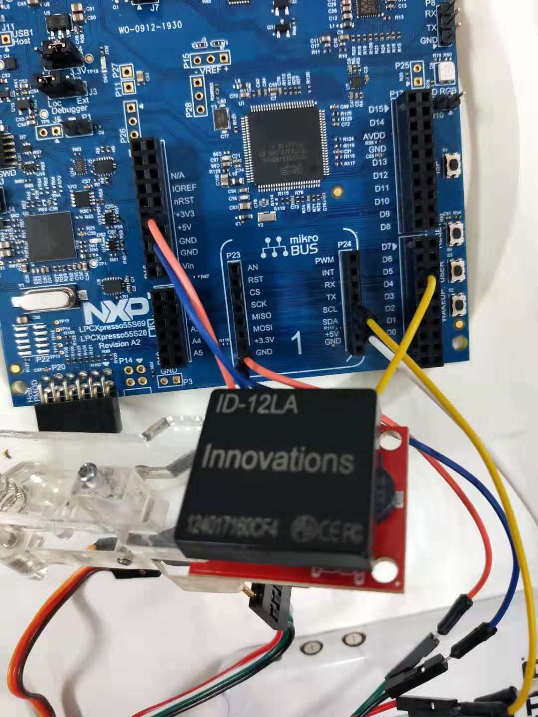
NFC读卡器的型号
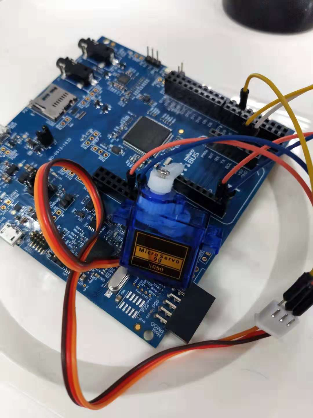
链接9G伺服电机
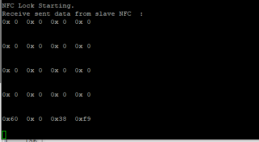
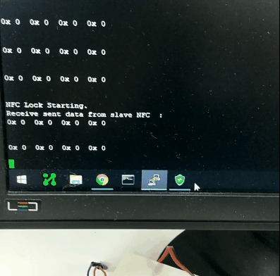
读卡器读取NFC卡的ID信息
四、演示视频
动态演示这个程序执行过程
五、项目文档
5.1 使用的硬件包括
- LPC55S69 dev board
- NFC tag reader ID-12LA,
5.2 主要的代码如下:其中实现servo控制使用了ctime库,定义一个50Hz的占空比再2.5%~12.5%可调的PWM信号来控制伺服电机。
int main(void)
{
    i2c_master_config_t masterConfig;
    status_t reVal        = kStatus_Fail;
    uint8_t deviceAddress = 0x01U;

          ctimer_config_t config;
    uint32_t srcClock_Hz;
    uint32_t timerClock;
                uint8_t        updatedutyCyclePercent;

    /* attach 12 MHz clock to FLEXCOMM0 (debug console) */
    CLOCK_AttachClk(BOARD_DEBUG_UART_CLK_ATTACH);

    /* attach 12 MHz clock to FLEXCOMM8 (I2C master) */
    CLOCK_AttachClk(kFRO12M_to_FLEXCOMM4);

            /* Use 12 MHz clock for some of the Ctimers */
    CLOCK_AttachClk(kFRO_HF_to_CTIMER2);

    /* reset FLEXCOMM for I2C */
    RESET_PeripheralReset(kFC4_RST_SHIFT_RSTn);

    BOARD_InitPins();
    BOARD_BootClockPLL150M();
    BOARD_InitDebugConsole();

    /* CTimer0 counter uses the AHB clock, some CTimer1 modules use the Aysnc clock */
    srcClock_Hz = CTIMER_CLK_FREQ;

    PRINTF("CTimer example to generate a PWM signalrn");

    CTIMER_GetDefaultConfig(&config);
    timerClock = srcClock_Hz / (config.prescale + 1);

    CTIMER_Init(CTIMER, &config);

    /* Get the PWM period match value and pulse width match value of 50hz PWM signal with 2.5%~12.5% dutycycle , 20ms peoriod*/
    CTIMER_GetPwmPeriodValue(50, 10, timerClock);
    CTIMER_SetupPwmPeriod(CTIMER, CTIMER_MAT_OUT, g_pwmPeriod, g_pulsePeriod, false);
    CTIMER_StartTimer(CTIMER);
                //CTIMER_UpdatePwmDutycycle(CTIMER_Type *base, ctimer_match_t matchChannel, uint8_t dutyCyclePercent);

    PRINTF("rnI2C board2board polling -- Master transfer.rn");

    g_master_txBuff[0] = I2C_DATA_LENGTH - 1U;
    for (uint32_t i = 1U; i < I2C_DATA_LENGTH; i++)
    {
        g_master_txBuff[i] = i - 1;
    }


    I2C_MasterGetDefaultConfig(&masterConfig);

    /* Change the default baudrate configuration */
    masterConfig.baudRate_Bps = I2C_BAUDRATE;

    /* Initialize the I2C master peripheral */
    I2C_MasterInit(EXAMPLE_I2C_MASTER, &masterConfig, I2C_MASTER_CLOCK_FREQUENCY);


    /* Wait until the slave is ready for transmit, wait time depend on user's case.
       Slave devices that need some time to process received byte or are not ready yet to
       send the next byte, can pull the clock low to signal to the master that it should wait.*/
    for (uint32_t i = 0U; i < WAIT_TIME; i++)
    {
        __NOP();
    }
    PRINTF("Receive sent data from slave :");

                while (1)
    {
    for (uint32_t i = 0U; i < WAIT_TIME; i++)
    {        __NOP();    }
    /* Receive blocking data from slave */
    if (kStatus_Success == I2C_MasterStart(EXAMPLE_I2C_MASTER, I2C_MASTER_SLAVE_ADDR_7BIT, kI2C_Write))
    {

        reVal = I2C_MasterReadBlocking(EXAMPLE_I2C_MASTER, g_master_rxBuff, I2C_DATA_LENGTH - 1, kI2C_TransferDefaultFlag);
        if (reVal != kStatus_Success)
        {
            return -1;
        }

        reVal = I2C_MasterStop(EXAMPLE_I2C_MASTER);
        if (reVal != kStatus_Success)
        {
            return -1;
        }
    }

    for (uint32_t i = 0U; i < 4; i++)
                    //for (uint32_t i = 0U; i < I2C_DATA_LENGTH - 1; i++)
    {
        if (i % 8 == 0)
        {
            PRINTF("rn");
        }
        PRINTF("0x%2x  ", g_master_rxBuff[i]);
                                if (g_master_rxBuff[i]== g_match_id[i] ){g_master_rxBuff[I2C_DATA_LENGTH-1]=127;}
    }
    PRINTF("rnrn");

                // LOCK_UNLOCK, refreshed every loop and return to LOCK off status,
                updatedutyCyclePercent= LOCK_ON ? (g_master_rxBuff[I2C_DATA_LENGTH-1]==127):LOCK_OFF;
                g_pulsePeriod = (g_pwmPeriod * (100 - updatedutyCyclePercent)) / 100;
                CTIMER_UpdatePwmDutycycle(CTIMER, CTIMER_MAT_OUT, g_pulsePeriod);

    }
    // PRINTF("rnEnd of I2C example .rn");
}
 芯耀
芯耀


 2421
2421

 下载ECAD模型


