TA的每日心情 | 奋斗
2018-8-29 20:40 |
|---|
签到天数: 1341 天 连续签到: 1 天 [LV.10]以坛为家III
|
利用IIC通信实现了对AT24C02的读写
首先看原理图

简单就是指放了一个IIC组件和两个数字IO
IIC组件的设置

但要注意两个数字IO的管教配置
每个IO要设置成双向,开漏低电平


引脚分配 当不适用IIC唤醒的话 IIC的 SDA 和 SCL 基本上也会是自由分配的

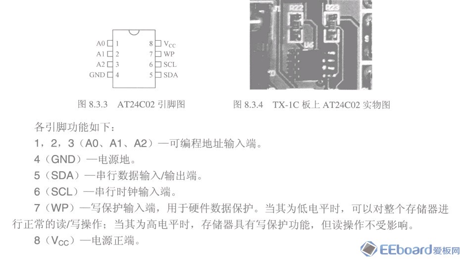
注意AT24C02的 电路连接 和 IIC通信的方法

主要代码
测试写入函数,address为要写入的芯片内部的地址,ver为写入的数据
注意的是 器件地址, 由于PSoC的IIC函数中,对器件地址的规定是除去 W/R 判断位之后的右对齐
比如说我的AT24C02 ,器件地址的高4位厂家规定为1010
我器件的A2 A1 A0 都接地 为 000,则在PSoC3 中 器件地址为1010000即 0x50
uint8 IIC_TestWriteByte(uint8 address, uint8 ver)
{
uint8 Status = 0;
uint8 slaveAddr = 0x50; // device address , not contain the last W/R and right align
uint8 count = 0;
uint8 add[2] = {0};
add[0] = address; // byte address
add[1] = ver; // data
I2C_MasterClearStatus();
I2C_MasterWriteBuf(slaveAddr, add, 2, I2C_MODE_COMPLETE_XFER);
Status = I2C_MasterStatus();
while(Status & I2C_MSTAT_XFER_INP) /* Waits till the transfer is complete */
{
count ++ ;
if(count == 255)
{
return Status;
}
Status = I2C_MasterStatus();
}
return Status;
// Status = 0x02 = I2C_MSTAT_WR_CMPLT = Write complete */
}
测试读取函数
uint8 IIC_TestReadByte(uint8 address)
{
uint8 Status = 0;
uint8 slaveAddr = 0x50; // device address not contain the last W/R and right align
uint8 count = 0;
uint8 add[1] = {0};
uint8 read_value[2] = {0};
add[0] = address; //byte address
I2C_MasterClearStatus();
I2C_MasterWriteBuf(slaveAddr, add, 1, I2C_MODE_NO_STOP);
Status = I2C_MasterStatus();
// Status should be I2C_MSTAT_WR_CMPLT | I2C_MSTAT_XFER_INP | I2C_MSTAT_XFER_HALT
while((Status & I2C_MSTAT_WR_CMPLT)==0)
{
count ++ ;
if(count == 255)
{
return Status;
}
Status = I2C_MasterStatus();
}
count = 0;
I2C_MasterReadBuf(slaveAddr, read_value, 1, I2C_MODE_REPEAT_START ); /* read_value will hold the two bytes read.This begins with a repeat start */
while(I2C_MasterStatus() & I2C_MSTAT_XFER_INP);
return read_value[0];
}
调试时候的截图

注意看到能够正确读取出写入的数据
实物图

|
|
 /4
/4 
 /4
/4 