TA的每日心情 | 擦汗
6 小时前 |
|---|
签到天数: 2331 天 连续签到: 413 天 [LV.Master]伴坛终老
|
由于此次底板的电压输入范围在18V~30V,推荐使用24V配24V电机,手头暂时没有合适的电机配套组件,只有一个12V并支持Hall的尼得科无刷直流电机,而根据从灵动微官方获取的SDK中,如需给板子直接上12V直流电让其工作正常,需要将U1拆除,并撤掉JP2上的跳线帽。但这样做的风险比较大,搞不好U1会因为拆焊而报废。

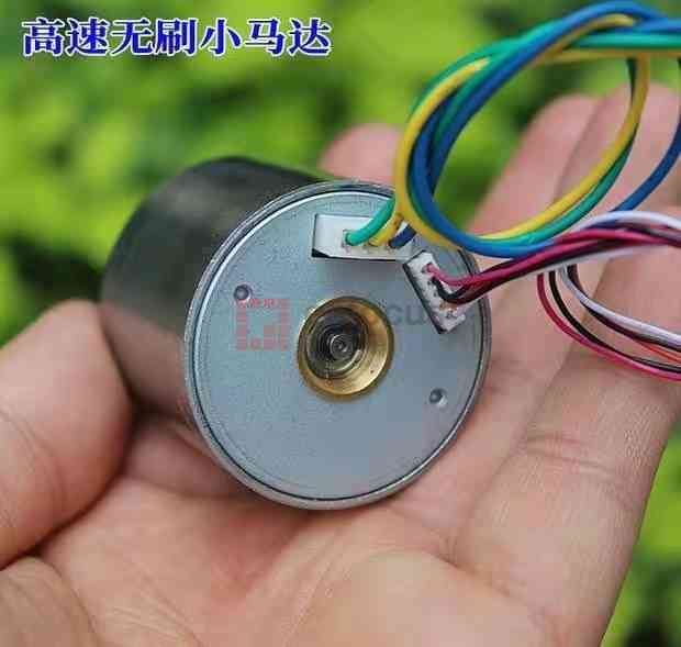
此次尝试使用官方提供的“MM32SPIN0230_HALL_FOC_2R_V_1.0”Demo工程来验证是否能使用12V正常驱动手头这个直流电机。这个直流电机的大致参数如下:

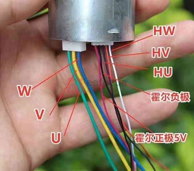
某宝上还提供了详细的接线示意图,对照一番,与此次的“Motor-DK电机控制板”接口分布相一致。


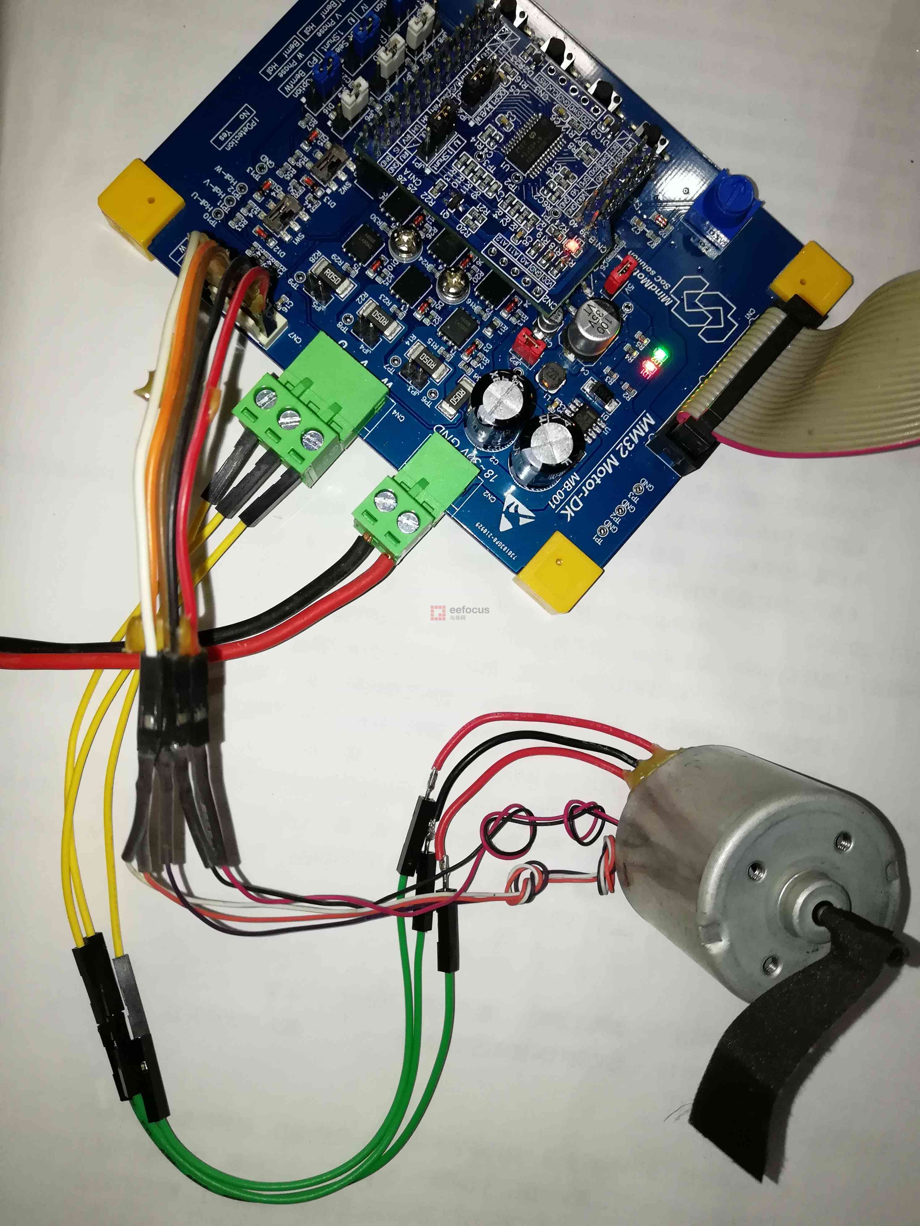
根据电机底板上的PCB丝印,可以将直流电机按照线序,正确连接到板子上。

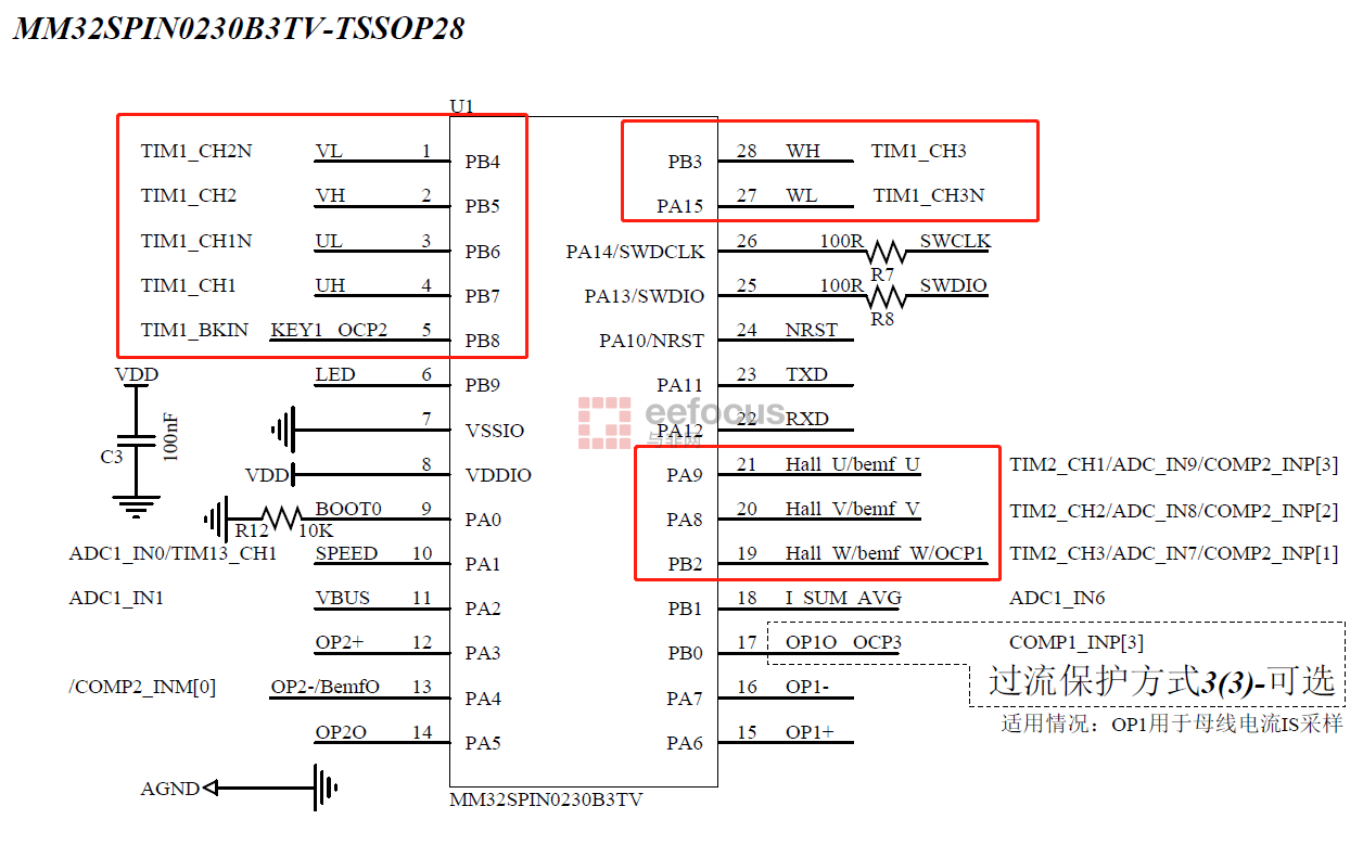
工程中的源码也是针对Mini型开发板的,因此需要注意LED管脚定义,由于底板是通用的接口,因此其它地方无需变动,编译完成后,直接下载到开发板中,结果电机没有任何反应。这可能还是因为供电不符合18V~30V的要求,看到其它坛友已通过该例程正常驱动24V电流电机了。工程部分源码提供如下:
- #include "board.h"
- #include "drv_inc.h"
- #include "parameter.h"
- #include "user_function.h"
- void Bsp_Op_Init(void)
- {
- GPIO_InitTypeDef GPIO_InitStructure;
- GPIO_StructInit(&GPIO_InitStructure);
- /* GPIO Ports Clock Enable */
- RCC_AHBPeriphClockCmd(OPAMP_GPIO_CLK, ENABLE);
- /*Configure GPIO pin : OPAMP1_Pin */
- GPIO_InitStructure.GPIO_Mode = GPIO_Mode_AIN;
- GPIO_InitStructure.GPIO_Pin = OPAMP1_INM_PIN;
- GPIO_Init(OPAMP1_INM_PORT, &GPIO_InitStructure);
- GPIO_InitStructure.GPIO_Pin = OPAMP1_INP_PIN;
- GPIO_InitStructure.GPIO_Mode = GPIO_Mode_AIN;
- GPIO_Init(OPAMP1_INP_PORT, &GPIO_InitStructure);
-
- /*Configure GPIO pin : OPAMP2_Pin */
- GPIO_InitStructure.GPIO_Mode = GPIO_Mode_AIN;
- GPIO_InitStructure.GPIO_Pin = OPAMP2_INM_PIN;
- GPIO_Init(OPAMP2_INM_PORT, &GPIO_InitStructure);
- GPIO_InitStructure.GPIO_Pin = OPAMP2_INP_PIN;
- GPIO_InitStructure.GPIO_Mode = GPIO_Mode_AIN;
- GPIO_Init(OPAMP2_INP_PORT, &GPIO_InitStructure);
- }
- void Bsp_Adc_Init(void)
- {
- GPIO_InitTypeDef GPIO_InitStructure;
- GPIO_StructInit(&GPIO_InitStructure);
-
- /* ADC Clock Enable */
- RCC_AHBPeriphClockCmd(ADC_GPIO_CLK, ENABLE);
- /*Configure ADC pin */
- GPIO_InitStructure.GPIO_Mode = GPIO_Mode_AIN;
- GPIO_InitStructure.GPIO_Pin = VR_PIN;
- GPIO_Init(VR_PORT, &GPIO_InitStructure);
- GPIO_InitStructure.GPIO_Pin = VBUS_PIN;
- GPIO_Init(VBUS_PORT, &GPIO_InitStructure);
- GPIO_InitStructure.GPIO_Pin = IR_V_PIN;
- GPIO_Init(IR_V_PORT, &GPIO_InitStructure);
- GPIO_InitStructure.GPIO_Pin = IR_U_PIN;
- GPIO_Init(IR_U_PORT, &GPIO_InitStructure);
- }
- void Bsp_Comp_Init(void)
- {
- GPIO_InitTypeDef GPIO_InitStructure;
- GPIO_StructInit(&GPIO_InitStructure);
-
- /* COMP Clock Enable */
- RCC_AHBPeriphClockCmd((COMP_GPIO_CLK), ENABLE);
- GPIO_InitStructure.GPIO_Pin = COMP_INP_PIN;
- GPIO_InitStructure.GPIO_Mode = GPIO_Mode_AIN;
- GPIO_InitStructure.GPIO_Speed = GPIO_Speed_High;
- GPIO_Init(COMP_INP_PORT, &GPIO_InitStructure);
- }
- void Bsp_Led_Init(void)
- {
- GPIO_InitTypeDef GPIO_InitStructure;
-
- GPIO_StructInit(&GPIO_InitStructure);
-
- /* LED Clock Enable */
- RCC_AHBPeriphClockCmd(LED_RCC_CLOCKGPIO, ENABLE);
-
- /*Configure GPIO pin : LED_Pin */
- GPIO_InitStructure.GPIO_Pin = LED1_PIN;
- GPIO_InitStructure.GPIO_Speed = GPIO_Speed_High;
- GPIO_InitStructure.GPIO_Mode = GPIO_Mode_Out_PP;
- GPIO_Init(LED1_PORT, &GPIO_InitStructure);
- }
- void Bsp_Hall_Init(void)
- {
- GPIO_InitTypeDef GPIO_InitStructure;
-
- GPIO_StructInit(&GPIO_InitStructure);
-
- /* HALL Clock Enable */
- RCC_AHBPeriphClockCmd(HALL_RCC_CLOCKGPIO, ENABLE);
-
- /*Configure GPIO pin : HALL_Pin */
- GPIO_InitStructure.GPIO_Pin = HALL_U_PIN;
- GPIO_InitStructure.GPIO_Mode = GPIO_Mode_IPU;
- GPIO_Init(HALL_U_PORT, &GPIO_InitStructure);
-
- GPIO_InitStructure.GPIO_Pin = HALL_V_PIN;
- GPIO_InitStructure.GPIO_Mode = GPIO_Mode_IPU;
- GPIO_Init(HALL_V_PORT, &GPIO_InitStructure);
-
- GPIO_InitStructure.GPIO_Pin = HALL_W_PIN;
- GPIO_InitStructure.GPIO_Mode = GPIO_Mode_IPU;
- GPIO_Init(HALL_W_PORT, &GPIO_InitStructure);
-
- GPIO_PinAFConfig(HALL_U_PORT, HALL_U_PIN_SOURCE, HALL_U_PIN_AF); //TIM2_CH1
- GPIO_PinAFConfig(HALL_V_PORT, HALL_V_PIN_SOURCE, HALL_V_PIN_AF); //TIM2_CH2
- GPIO_PinAFConfig(HALL_W_PORT, HALL_W_PIN_SOURCE, HALL_W_PIN_AF); //TIM2_CH3
- }
- void Bsp_Pwm_Init(void)
- {
- GPIO_InitTypeDef GPIO_InitStructure;
- GPIO_StructInit(&GPIO_InitStructure);
- /* PWM Clock Enable */
- RCC_AHBPeriphClockCmd(BLDC1_GPIO_CLK, ENABLE);
- /*Configure GPIO pin : PWM_Pin */
- GPIO_InitStructure.GPIO_Pin = BLDC1_UH_PIN;
- GPIO_InitStructure.GPIO_Speed = GPIO_Speed_High;
- GPIO_InitStructure.GPIO_Mode = GPIO_Mode_AF_PP;
- GPIO_Init(BLDC1_UH_PORT, &GPIO_InitStructure);
- GPIO_InitStructure.GPIO_Pin = BLDC1_VH_PIN;
- GPIO_Init(BLDC1_VH_PORT, &GPIO_InitStructure);
- GPIO_InitStructure.GPIO_Pin = BLDC1_WH_PIN;
- GPIO_Init(BLDC1_WH_PORT, &GPIO_InitStructure);
- GPIO_InitStructure.GPIO_Pin = BLDC1_UL_PIN;
- #if PWM_L_USE_IO
- GPIO_InitStructure.GPIO_Mode = GPIO_Mode_Out_PP;
- #endif
- GPIO_Init(BLDC1_UL_PORT, &GPIO_InitStructure);
- GPIO_InitStructure.GPIO_Pin = BLDC1_VL_PIN;
- GPIO_Init(BLDC1_VL_PORT, &GPIO_InitStructure);
- GPIO_InitStructure.GPIO_Pin = BLDC1_WL_PIN;
- GPIO_Init(BLDC1_WL_PORT, &GPIO_InitStructure);
- /*selects the pin to used as Alternate function of PWM*/
- GPIO_PinAFConfig(BLDC1_UH_PORT, BLDC1_UH_PIN_SRC, BLDC1_UH_PIN_AF);
- GPIO_PinAFConfig(BLDC1_VH_PORT, BLDC1_VH_PIN_SRC, BLDC1_VH_PIN_AF);
- GPIO_PinAFConfig(BLDC1_WH_PORT, BLDC1_WH_PIN_SRC, BLDC1_WH_PIN_AF);
- #if PWM_L_USE_TIM
- GPIO_PinAFConfig(BLDC1_UL_PORT, BLDC1_UL_PIN_SRC, BLDC1_UL_PIN_AF);
- GPIO_PinAFConfig(BLDC1_VL_PORT, BLDC1_VL_PIN_SRC, BLDC1_VL_PIN_AF);
- GPIO_PinAFConfig(BLDC1_WL_PORT, BLDC1_WL_PIN_SRC, BLDC1_WL_PIN_AF);
- #endif
- #if PWM_L_USE_IO
- GPIO_ResetBits(BLDC_UL_PORT, BLDC_UL_PIN);
- GPIO_ResetBits(BLDC_VL_PORT, BLDC_VL_PIN);
- GPIO_ResetBits(BLDC_WL_PORT, BLDC_WL_PIN);
- #endif
- }
- void Bsp_Gpio_Init(void)
- {
- Bsp_Op_Init();
- Bsp_Led_Init();
- Bsp_Hall_Init();
- Bsp_Adc_Init();
- Bsp_Comp_Init();
- Bsp_Pwm_Init();
- }
- void Board_ADC_Init(void)
- {
- /*ADC RANK Array*/
- ADC_Channel_TypeDef sUserAdc1Channel[4];
- /* Configure the ADC RANK Sequence*/
- sUserAdc1Channel[0].u8Rank = IR_U_RANK;
- sUserAdc1Channel[0].sAdcChannel = IR_U_CHANNEL;
- sUserAdc1Channel[0].pNext = &sUserAdc1Channel[1];
-
- sUserAdc1Channel[1].u8Rank = IR_V_RANK;
- sUserAdc1Channel[1].sAdcChannel = IR_V_CHANNEL;
- sUserAdc1Channel[1].pNext = &sUserAdc1Channel[2];
-
- sUserAdc1Channel[2].u8Rank = VBUS_RANK;
- sUserAdc1Channel[2].sAdcChannel = VBUS_CHANNEL;
- sUserAdc1Channel[2].pNext = &sUserAdc1Channel[3];
-
- sUserAdc1Channel[3].u8Rank = VR_RANK;
- sUserAdc1Channel[3].sAdcChannel = VR_CHANNEL;
- sUserAdc1Channel[3].pNext = NULL;
-
- /* Select the ADC external trigger source of the ADC is T1_CC5*/
- Drv_Adc_Basic_Init(ADC1, ADC_ExtTrig_T1_CC4);
- /* Select the ADC sample time*/
- Drv_Adc_Channel_Init(ADC1, sUserAdc1Channel, ADC_SampleTime_2_5);
- ADC_Cmd(ADC1, ENABLE);
- }
- volatile COMP_TypeDef *pComp;
- void Board_Comp_Init(void)
- {
- COMP_Input_TypeDef sUserCompInput;
- /* Select the inverting input of the comparator */
- sUserCompInput.sCompInvertingInput = COMP_INVERTING;
- /* Select the non inverting input of the comparator*/
- sUserCompInput.sCompNonInvertingInput = COMP_NON_INVERTING;
- /* Select comparator external reference voltage */
- sUserCompInput.u8CompCrvSelect = COMP_CRV_VOLTAGE_SELECT;
- /* Initializes the COMP according to the specified parameters in the COMP_Input_TypeDef */
- Drv_Comp_Init(&sUserCompInput);
- }
- void Board_Opamp_Init(void)
- {
- /* op-amp Clock Enable */
- RCC_APB1PeriphClockCmd(RCC_APB1ENR_OPA1_Msk, ENABLE);
- RCC_APB1PeriphClockCmd(RCC_APB1ENR_OPA2_Msk, ENABLE);
- /*Enable the specified OPAMP peripheral*/
- OPAMP_Cmd(OPAMP1,ENABLE);
- OPAMP_Cmd(OPAMP2,ENABLE);
- }
- void Peripheral_Init(void)
- {
- Board_ADC_Init();
- Board_Comp_Init();
- Board_Opamp_Init();
- Drv_Hall_Init(TIM2_PRIOD, TIM2_PSC_LOAD);
- Drv_Pwm_Init(TIM1, PWMPERIOD, DEAD_TIME);
- Drv_Iwdg_Init();
-
- /*Initialize divider*/
- Drv_Hwdiv_Init();
-
- /** Enable the TIM1 */
- TIM_Cmd(TIM1, ENABLE);
- }

|
|
 /2
/2 
 /2
/2 