|
STM32F4DiscoveryRTC调试手记 实现功能:配置RTC实现计时功能,并通过唤醒中断输出当前时间。 一、硬件改动 本次调试使用32768Hz晶振,而STM32F4Discovery上并未焊接该晶振,于是硬件需要作出几个改动: 1.

焊接晶振X3 32768Hz(负载电容为6pF)C16、C27 6pF 2.

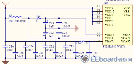
因VBAT直接接到VDD上了,而RTC需要电池供电支持,因而需要拆掉R26,并在VBAT那个焊盘接电池正极 硬件改动效果图: 二、所使用的库函数 在本次实验中,主要使用了stm32f4xx_pwr.c,stm32f4xx_rcc.c, stm32f4xx_rtc.c中的函数,下面对部分函数进行简单的介绍: stm32f4xx_pwr.c: PWR_BackupAccessCmd:通过位带实现设置PWR_CR[8] DBP,该位用于使能/失能RTC、RTC备份寄存器及备份SRAM的访问。 stm32f4xx_rcc.c: RCC_LSEConfig:实现对RCC_BDCR寄存器的设置,主要是对[2]LSEBYP和[0]LSEON进行设置。这里用于启动32768Hz晶振。 RCC_RTCCLKConfig:实现对RCC_BDCR[9:8]RTCSEL设置,用于选择RTC时钟的时钟源。同时,可能对RCC_CFGR[20:16]RTCPRE设置(使用HSE作为RTC时钟时设置)。 RCC_RTCCLKCmd:位带操作实现对RCC_BDCR[15]RTCEN设置,用于使能/失能RTC。 stm32f4xx_rtc.c: 首先先看三个结构体: typedef struct { uint32_t RTC_HourFormat; /*!<Specifies the RTC Hour Format. This parameter canbe a value of @ref RTC_Hour_Formats */ uint32_t RTC_AsynchPrediv; /*!< Specifies the RTC AsynchronousPredivider value. This parametermust be set to a value lower than 0x7F*/ uint32_t RTC_SynchPrediv; /*!<Specifies the RTC Synchronous Predivider value. This parametermust be set to a value lower than 0x7FFF */ }RTC_InitTypeDef; 此结构体用于RTC_Init,即RTC初始化。 其中,RTC_HourFormat影响RTC_CR[6] FMT:时钟格式,该位影响时钟的表达方式:AM/PM或24小时表达方式。 RTC_AsynchPrediv和RTC_SynchPrediv则影响RTC_PRER寄存器的值, RTC_AsynchPrediv影响[22:16]PREDIV_A[6:0],该值决定ck_apre的频率。 ck_apre = RTCCLK/(PREDIV_A + 1) RTC_SynchPrediv影响[14:0]PREDIV_S,该值决定ck_spre频率。 ck_spre = ck_apre/( PREDIV_S + 1) 因此处采用32768Hz晶振,为生成1Hz时钟,故使用: RTC_InitStructure.RTC_SynchPrediv = 0xFF; RTC_InitStructure.RTC_AsynchPrediv = 0x7F; typedef struct { uint8_t RTC_Hours; /*!<Specifies the RTC Time Hour. This parameter must be set to a valuein the 0-12 range if theRTC_HourFormat_12 is selected or 0-23 range if the RTC_HourFormat_24is selected. */ uint8_t RTC_Minutes; /*!<Specifies the RTC Time Minutes. This parameter must beset to a value in the 0-59 range. */ uint8_t RTC_Seconds; /*!<Specifies the RTC Time Seconds. This parameter must beset to a value in the 0-59 range. */ uint8_t RTC_H12; /*!<Specifies the RTC AM/PM Time. This parameter can be avalue of @ref RTC_AM_PM_Definitions */ }RTC_TimeTypeDef; typedef struct { uint8_t RTC_WeekDay; /*!< Specifies the RTC Date WeekDay. This parameter can be avalue of @ref RTC_WeekDay_Definitions */ uint8_t RTC_Month; /*!<Specifies the RTC Date Month (in BCD format). This parameter can be avalue of @ref RTC_Month_Date_Definitions */ uint8_t RTC_Date; /*!< Specifies the RTC Date. This parameter must beset to a value in the 1-31 range. */ uint8_t RTC_Year; /*!<Specifies the RTC Date Year. This parameter must beset to a value in the 0-99 range. */ }RTC_DateTypeDef; 上述两个结构体用于保存时间或日期,格式可以为BCD码或二进制数,注意年份RTC_Year的取值范围为0-99。 下面是RTC部分函数。 RTC_Init:RTC初始化 RTC_EnterInitMode:用于设置RTC_ISR(RTC初始化和状态寄存器)[7]INIT初始化模式,在初始化模式下,RTC_TR、RTC_CR、RTC_PRER均可修改。计时停止直至INIT复位。 RTC_ExitInitMode:复位RTC_ISR[7]INIT。 时间配置及获取函数: ErrorStatus RTC_SetTime(uint32_tRTC_Format, RTC_TimeTypeDef* RTC_TimeStruct); void RTC_GetTime(uint32_tRTC_Format, RTC_TimeTypeDef* RTC_TimeStruct); ErrorStatus RTC_SetDate(uint32_tRTC_Format, RTC_DateTypeDef* RTC_DateStruct); void RTC_GetDate(uint32_tRTC_Format, RTC_DateTypeDef* RTC_DateStruct); 这几个函数实现对RTC_TR和RTC_DR的访问获得当前时间及日期。最终,存入这两个寄存器的值为BCD码。而这些函数第二个参数的结构体中所存入的值可以为BCD码,也可以为二进制数,其格式由第一个参数(RTC_Format_BIN/RTC_Format_BCD)指定。 唤醒中断相关函数: RTC_WakeUpClockConfig:影响RTC_CR[2:0]WUCKSEL,确定唤醒时钟ck_wut的时钟源。 RTC_SetWakeUpCounter:设置RTC_WUTR[15:0]WUT,当WUTE=1时,WUTF标志位每隔(WUT+1)个ck_wut时钟周期置位。 RTC_WakeUpCmd:影响RTC_CR[10]WUTE唤醒时钟使能位。 备份寄存器: 在STM32F1中是在stm32f10x.bkp.c中实现,这里由RTC实现了。 RTC_WriteBackupRegister、RTC_ReadBackupRegister实现对相应备份寄存器的读写。 中断相关: RTC_ITConfig:影响RTC_CR[15]TSIE时间戳中断使能、[14]WUTIE唤醒时钟中断使能、[13-12]ALRA(B)IE:闹铃A/B中断使能。 三、初始化流程及代码 初始化流程大致如下: 1) 使能时钟,配置RTC时钟及分频比,获得1Hz的ck_spre时钟。 2) 配置NVIC相关参数 3) 唤醒中断配置。因此处需要实现秒中断,故采用ck_spre时钟作为ck_wut时钟源,唤醒时钟计数器设置为0,则可实现秒中断。 static void RTC_Configuration(void) { RTC_InitTypeDefRTC_InitStructure; /*Enable PWR and BKP clocks */ RCC_APB1PeriphClockCmd(RCC_APB1Periph_PWR, ENABLE); /*Allow access to BKP Domain */ PWR_BackupAccessCmd(ENABLE); /*Enable LSE */ RCC_LSEConfig(RCC_LSE_ON); /*Wait till LSE is ready */ while (RCC_GetFlagStatus(RCC_FLAG_LSERDY) == RESET) {} /*Select LSE as RTC Clock Source */ RCC_RTCCLKConfig(RCC_RTCCLKSource_LSE); /*Enable RTC Clock */ RCC_RTCCLKCmd(ENABLE); /*Wait for RTC registers synchronization */ RTC_WaitForSynchro(); /*RTC Init */ RTC_InitStructure.RTC_HourFormat= RTC_HourFormat_24; //24 hour format //32768/ (1 + 0x7F) = 32768 /128 = 256Hz, //256/ (1 + 0xFF) = 1Hz, This is the calender frequecy~ RTC_InitStructure.RTC_SynchPrediv= 0xFF; RTC_InitStructure.RTC_AsynchPrediv= 0x7F; if(RTC_Init(&RTC_InitStructure) == ERROR) printf("\r\nRTCinit failed"); else printf("\r\nRTCinit success"); /*NVIC configuration */ NVIC_Configuration(); RTC_WakeUpCmd(DISABLE); //important //Configure the RTC WakeUp Clock source: CK_SPRE (1Hz) RTC_WakeUpClockConfig(RTC_WakeUpClock_CK_SPRE_16bits); RTC_SetWakeUpCounter(0x0); RTC_WakeUpCmd(ENABLE); RTC_ClearITPendingBit(RTC_IT_WUT); RTC_ITConfig(RTC_IT_WUT,ENABLE); } 中断配置流程见RM009023.5节RTC interrupt 使能唤醒中断初始化序列: 1) 配置并使能EXTI Line22进入中断模式并选择上升沿触发。 2) 在NVIC中配置RTC_WKUP_IRQ 3) 配置RTC来产生RTC唤醒时钟事件 static void NVIC_Configuration(void) { NVIC_InitTypeDef NVIC_InitStructure; EXTI_InitTypeDefEXTI_InitStructure; /*EXTI Configuration */ EXTI_ClearITPendingBit(EXTI_Line22); EXTI_InitStructure.EXTI_Line= EXTI_Line22; EXTI_InitStructure.EXTI_Mode= EXTI_Mode_Interrupt; EXTI_InitStructure.EXTI_Trigger= EXTI_Trigger_Rising; EXTI_InitStructure.EXTI_LineCmd= ENABLE; EXTI_Init(&EXTI_InitStructure); /*Configure one bit for preemption priority */ NVIC_PriorityGroupConfig(NVIC_PriorityGroup_1); /*Enable the RTC Interrupt */ NVIC_InitStructure.NVIC_IRQChannel = RTC_WKUP_IRQn; NVIC_InitStructure.NVIC_IRQChannelPreemptionPriority = 1; NVIC_InitStructure.NVIC_IRQChannelSubPriority = 0; NVIC_InitStructure.NVIC_IRQChannelCmd = ENABLE; NVIC_Init(&NVIC_InitStructure); } 实验结果如下 RTC还有许多功能,如闹铃、时间戳等,有待大家去发掘^ ^
|  /1
/1 
 /1
/1 